Showing posts with label ELECTRONIC MINI PROJECTS. Show all posts

mini projects for ece,mini projects for electronics and communication


FM transmitter using UPC1651
Here is the circuit diagram of an FM transmitter using the IC UPC1651. UPC1651 is a wide band UHF Silicon MMIC amplifier. The IC has a broad frequency response to 1200MHz and power gain up to 19dB.The IC can be operated from 5V DC.
The audio signals picked by the microphone are fed to the input pin (pin2) of the IC via capacitor C1. C1 acts as a noise filter. The modulated FM signal will be available at the output pin (pin4) of the IC. Inductor L1 and capacitor C3 forms the necessary LC circuit for creating the oscillations. Frequency of the transmitter can be varied by adjusting the capacitor C3.


ece projects,electronic circuits,Low Cost Burglar Alarm For Boats ,simple ckts for mini projects


Low Cost Burglar Alarm For Boats 

This low-cost burglar alarm employs a 12V strobe light and a truck reversing horn as the visible and audible alarm outputs while the alarm itself is a 12V horn relay and some pressure mat switches. This simple approach has the benefit that the alarm continues to operate even if the entry point is immediately closed and it draws no current while in the armed condition. To make it independent of the boat supply it runs from a single 12V or two 6V alkaline lantern batteries connected in series. These should last well in excess of two years. An advantage of a lantern battery is that it will last less than an hour while powering the alarm in its active role.

This means the alarm system will not seriously contravene noise pollution laws. If there are very strict noise regulations in your area, you can fit an alarm timer, available from some electronic shops, in the circuit between the battery positive and the key switch. The key switch can be installed in the cockpit bulkhead and connects to two normally open (NO) switches wired in parallel. One switch is a pressure mat placed on the cockpit floor near the entry, underneath a suitable piece of carpet or pliable cover. If a pressure mat is unsuitable, the main entry can be protected by a mechanical switch such as an automobile boot lid or door courtesy light switch.

Circuit diagram:

Low Cost Burglar Alarm Circuit Diagram

The second switch can be used to protect against entry through a forward hatch or second wheelhouse door. Any number of normally open (NO) switches can be installed in this system, all wired in parallel. If the alarm is tripped, the relay closes and latches on due to the wiring of its contacts and the horn and strobe light are powered. The suggested truck reversing horn is the Hella 6023 intermittent reversing buzzer which has an 85dB sound level and a current drain of 0.9A at 12V. The suggested strobe is a Hella 1657 which has an amber lens in a weatherproof housing. This strobe flashes about once per second and the current drain at 12V is 0.25A. The strobe can be installed outside on deck or in the main cabin where its flash will be seen through most ports and windows. Wiring to both the warning horn and strobe light should be concealed.

 keywords of site:
asbestos law firm,refinance a housebest student loanconference call service providersdallas dwi lawyersdelaware mesothelioma lawyershouston mesotheliomalawyersmesothelioma lawyers houstomalignant mesothelioma pleural rate survival asbestos attorney ill inoisillinois mesothelioma lawyers
asbestos attorney washingtonmesothelioma attorney tennesseecolorado mesothelioma lawyers asbestos attorneys philadelphia

electronic and communication seminar,latest ece seminars,electronics circuit kit ,

Fridge door Alarm

Beeps if you leave open the door over 20 seconds

3V battery operation, simple circuitry

 http://lh5.ggpht.com/_FdGFE8NBDgc/S5imO7wds3I/AAAAAAAACIE/_UxCwB2E-k0/s1024/fridge-door-open-alarm-complete.jpg


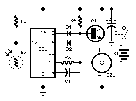
Circuit diagram:
Fridge alarm circuit diagram

Parts:

R1____________10K   1/4W Resistor
R2___________Photo resistor (any type)
R3,R4________100K   1/4W Resistors

C1____________10nF  63V Polyester Capacitor
C2___________100µF  25V Electrolytic Capacitor

D1,D2_______1N4148  75V 150mA Diodes

IC1___________4060  14 stage ripple counter and oscillator IC

Q1___________BC337  45V 800mA NPN Transistor

BZ1__________Piezo sounder (incorporating 3KHz oscillator)

SW1__________Miniature SPST slide Switch

B1___________3V Battery (2 AA 1.5V Cells in series)

Circuit operation:

This circuit, enclosed into a small box, is placed in the fridge near the lamp (if any) or the opening. With the door closed the interior of the fridge is in the dark, the photo resistor R2 presents a high resistance (>200K) thus clamping IC1 by holding pin 12 high. When a beam of light enters from the opening, or the fridge lamp illuminates, the photo resistor lowers its resistance (<2K), pin 12 goes low, IC1 starts counting and, after a preset delay (20 seconds in this case) the piezo sounder beeps for 20 sec. then stops for the same lapse of time and the cycle repeats until the fridge door closes. D2 connected to pin 6 of IC1 allows the piezo sounder beeping 3 times per second.